In the House of Oddbloke, we’re about to convert our integral garage into a dining room. We’re just waiting for our pet builder to finish his current project.
Whilst wasting my time on T’Internet one day I came across this photo, and showed it to my wife:

I couldn’t find much information on it, and most of what I did find was written in Spanish. It was by an up-market flooring company who specialise in custom jobs – your coat of arms inlaid across your ballroom in the west wing, that sort of thing.
My wife and I loved the idea of doing something similar in our dining room. It could be subtle: we’d have the lizards slightly larger so that the pattern wasn’t so intense. We’d stick with the same colour flooring for all tiles – the change in grain direction would still highlight the shapes clearly. Perhaps we’d just put the occasional darker lizard in, just to break things up a bit. And we couldn’t help thinking that this sort of opportunity wouldn’t come up again – we’re adding a new room rather than redecorating an existing one, so it feels like a bit more of a “blank canvas”.
So I spent some time looking for flooring companies that offered to CNC-mill or laser-cut flooring, and asked for rough quotes. They refused to offer even ballpark figures without data to work with. So: we create the data first, then bug the engineering companies later. And it’ll make an interesting project, too.
Reference Material
A quick Google image search produces no end of material for Escher Lizards, so getting reference material is not a problem.
The problem is that creating a template from a low-res JPEG of a lizard just won’t do it. Though the scale of the lizard is not critical (I could scale them up or down to any size I want) the exact shape of the lizard is vitally important. A tile must be able to tessellate perfectly with other instances of itself. That means that just using a vector package to trace a picture “by eye” won’t be sufficient. If any edges are off by anything more than a millimetre then the tiles won’t interlock.
I’m a programmer, and this is an engineering problem, so naturally I turn to computers for my solution. What I need is to write a program which will calculate all the co-rdinates exactly, so that I can guarantee that my shape will tessellate. Then I need to talk to the laser-cutting companies and find out what form I should export my data so they can use it directly.
The Mechanics of Tessellation
We’ve all seen Escher’s work, probably even from primary school. We know what tessellation is all about … but have you ever really studied how they work, and how you might implement software to do it? It can make your brain ache.
Here is a very simplistic video of the lizards tessellate. It’s a bit Powerpoint-ish, but it shows the process extremely clearly.
So we can see that each lizard is actually a hexagon which has been deformed. Shapes are cut away from some sides of the hexagon, then rotated and re-applied to other sides. The important part to remember – the technique that ensures the shapes tessellate – are Escher’s rules that describe exactly where the cut-section should be re-attached.
The way it works is this: of the six points that make up a hexagon, we consider every alternate one to be a “pivot” point. When cutting a chunk out of a side, you rotate it around the closest pivot point so that you’re gluing the chunk on to the “mirrored” side.
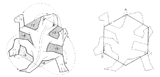
How Escher creates a lizard from a hexagon – with pivot points marked.
The above example was apparently drawn by Escher. In it you can see the three pivot points (marked A, B and C). Look carefully at the lizard’s head – can you see that this is an exact rotation of the space between his head and left arm? And can you see that the left arm is a rotation of the gap between his head and his right arm? So we know that all the corruption of the hexagon’s top-two sides are rotations around pivot A. And so on.
Design of the software
For purposes of editing a hexagon in software, I’m going to stop thinking of the process as cutting shapes out of a solid hexagon. Instead, I consider the hexagon as a list of points – joined by straight lines – which may be moved. Then, the software will function like this:
- The initial six points of the hexagon are immovable. They’re reference points.
- The software will allow the user to insert new points anywhere around the edge of the hexagon. When the user inserts a point, the software automatically creates the corresponding “mirror” point, around the other side of the pivot point.
- When the user selects a created point and drags it, its position is updated. After that point is moved, the location of the “mirrored” point (using the pivot point as the centre of rotation) is recalculated and updated too.
- In this way, as the user edits the shape, the software will guarantee that it is still perfectly tessellatable by recalculating all the “mirrored” points.
This will give me a list of 2D co-ordinates, describing a shape that tessellates perfectly. In theory, anyway.
Implementation
I have implemented the software in RISC OS, running on a Risc PC (and sometimes on a Raspberry Pi). I’ve done this just because it’s a nice, quick way to get something running. Writing a fullscreen program, reading mouse movement, drawing simple graphics and a fair number of maths calculations is nice and straightforward on RISC OS. And this program is only for my benefit, so it doesn’t matter that no-one else can run it.
There’s probably not much to say about the actual implementation of the software. But if you’re planning on doing something like this yourself, I’d recommend you take your time. Don’t take shortcuts. It’s worth spending a bit of time building a proper vector class, implementing some common vector operations, and so on. It’ll make your “main” logic so much easier to read. Also: when it comes to co-ordinates and maths operations on them, use as high precision as you can. The worry of compound rounding errors is a very real one, and it’s not worth the pathetic amount of performance saving you might get by sticking with integers.
Screenshots
(Click on any image to see full-size version.)

Simple hexagon, with six points. Numbers are drawn mostly for debugging purposes. The odd-numbered points (the yellow ones) are the pivots.

I created point 1, and then point 3 was automatically created and positioned by the software.

I dragged point 3 out, and the software automatically adjusted point 1 to suit. In this image you can also see the red line denoting where the hexagon *should* be, so you can see how it is deformed.

Testing that I can insert more points, and that it creates the mirror points each time.

Given enough points, enough time, an infinite number of monkeys, and some reference from Google Images, I can come up with a reasonable approximation of a lizard.

Same lizard, with the numbering turned off.

With the tile-mode on, to show how it would look when repeated.
A quick bit of code to export the data as Drawfiles and DXF, and I’m good to go. Now I need to see about turning it into something real, and prove my numbers.
[Part 2] [Part 3] [Part 4] [Part 5] [Part 6] [Part 7] [Part 8]
Floor looks great. Thanks for the step-by-step guide.
Hello,
very nice job and remarkable groundwork (the lizard drawing tool).
I would like to ask for you final dxf-file of your lizard (I hope to open it in LibreCAD – did you try ?) to make a small puzzle for my kids.
Thanks Sven
I really like your floor idea. I would also love to get hold of the dxf file if you are willing. I created a foam puzzle version of this on a laser cutter, and it works quite well but it was created from a bitmap so I am sure it’s nowhere near as clean as yours, and won’t scale as well. Nice work!
I don’t feel able to share the data – I understand that the Escher estate still pursue any potential copyright infringement. This was just a personal project, so the purpose of the writeup was really to explain my algorithms. But it’s unlikely I could ever turn this into a business. I’d have to start doing my own shape designs.
hello, I write from france to know if you would care to share your data.
I read with lots of interests your job which was so great and gorgious! we search such this idea for our corridor (just 6m2) but we are not so good in informatic as you to make the data: we are musicians!!!! but we are so fan to escher that we found your idea in looking for such thing in internet! I was so exciting reading your job. so I ask today even if I understand that you don’t want make a business or in the event that… thank you in any case for your creativity! great to see this!
absolutely brilliant. excellent work, and very fun write up!
Love the little software you wrote up. Helpful for visualizing where the alternate angle point will go.