(Keywords: MSF, Arduino, Cumbria, Rugby, Library, Example, Hitachi, LCD, 60kHz)
If you ever want to really annoy me, a good way of doing it is to tell me that you deliberately set your clocks ten minutes fast because “otherwise, I’d be late for all my appointments”. I have killed people for less than that.
Knowing the right time is one of my little obsessions. It doesn’t have to be accurate down to the microsecond (I’m not that bad!) but certainly to within a few seconds.
All my home computers adjust their time by NTP. My wristwatch, and any clock in the house which is “mine” (as opposed to my wife’s) has a Rugby MSF receiver. And some of my wife’s look like they’d make suitable projects for modification …
If I’m going to build any time-related projects, I’m going to try my hardest to include MSF support. The mini-project I describe here just shows how I receive and decode an MSF signal, to use as a building-block in other projects.
The receiver
I love eBay for getting hold of components. MSF decoders can be purchased for around a tenner, and take all the hard work out of the hardware side. The one I bought looks like this:
 As you can see, it even comes with an aerial wound to the correct frequency (60kHz for the UK, 77.5kHz for mainland Europe).
There are four connections on the board – the supply voltage (anything between 3v and 5v is fine), ground, the enable line, and the signal out.
The enable line is present so that you can optionally put the receiver into “sleep” mode when your microcontroller doesn’t need it. As the receiver only pulls a maximum of 10mA (but typically around half that) when running, I tend to keep it permanently-on for simplicity – just tie the enable line to 0v.

The receiver board features a surface mount LED so you can easily see that your aerial is connected and aligned correctly – you should see it flash around once a second, with a long flash (about half a second) marking the beginning of each minute.
The signal-out connection should be connected directly to a digital-in pin of your microcontroller – for this project, I’m using digital pin 3 of an Arduino Nano.
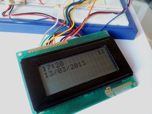
For a display, I’m using a common-as-muck Hitachi LCD display I had knocking around. But if you don’t have one of those, I’ve left some serial prints in the example code (commented-out) you can see with the serial monitor.
The software
Credit for the decoding-logic should go to Jarkman (website here) as all the hard stuff is his work! My involvement has been to strip-out the dependency on the Arduino “Time” library and made the code more ‘passive’.
The library works by registering an interrupt whenever the digital pin changes (goes from high to low, or low to high). By timing these changes, the code determines whether these pulses mark the beginning of the minute, a binary 0 (a short pulse) or a binary 1 (a longer pulse).
When a minute of binary data has been stored, the MSFDecoder library attempts to decode it. If it passes the checks (parity, plus some guaranteed patterns as specified in the MSF standard) then the decoded time is stored in the MSF instance, and flagged as valid.
It is then up to the host code to read this new date and time, act on it, and then clear the valid flag.
I have modified the code to work in this slightly-indirect manner because I expect most of my time-based projects to use an RTC module … so I want my projects to rely on that for time information, and then just adjust it on a daily basis if a valid MSF time is received (say, at 5am).
Example code
Here is a very minimal example sketch that uses the MSFDecoder library, and drives the Hitachi display:
// MSFDecoderExample
// Simple Arduino sketch that demonstrates use of MSFDecoder library.
// Kris Adcock 9th March 2013

#include <LiquidCrystal.h>
#include <MSFDecoder.h>

MSFDecoder MSF; // our instance of the decoder library,
// Only one possible per project! (But then, why would you have more than one decoder connected?)

LiquidCrystal lcd(12 /*RS*/, 11 /*Enable*/, 7 /*D4*/, 8 /*D5*/, 9 /*D6*/, 10 /*D7*/); // Our lcd module

bool g_bPrevCarrierState;
byte g_iPrevBitCount;
// These globals are just to prevent needless updating of the screen.
// Whether YOU need them or not depends on your project.

// Anything relating to serial debugging has been commented-out. Feel free to re-add it if you don't have an
// LCD module.

void setup()
{
  MSF.init();
  lcd.begin(16, 4);
  //Serial.begin(115200);
  g_bPrevCarrierState = false;
  g_iPrevBitCount = 255;
}

void loop()
{
  // print current progress of decoding.
  // (Only really done for reasons of feedback - you could happily ignore this if you don't need it.)
  bool bCarrierState = MSF.getHasCarrier();
  byte iBitCount = MSF.getBitCount();
  if ((bCarrierState != g_bPrevCarrierState) || (bCarrierState == true && iBitCount != g_iPrevBitCount))
  {
    lcd.setCursor(14, 0);

    if (bCarrierState)
    {
      if (iBitCount < 10) lcd.print('0');
      lcd.print(iBitCount);

      //Serial.print(iBitCount);
    } else
    {
      lcd.print("--");
      //Serial.print("--");
    }
  }
  g_bPrevCarrierState = bCarrierState;
  g_iPrevBitCount = iBitCount;

  // check if there's a freshly-decoded time in the decoder ...
  if (MSF.m_bHasValidTime)
  {
    // yep!

    char buffer[20];

    sprintf(buffer, "%02d:%02d", MSF.m_iHour, MSF.m_iMinute);
    lcd.setCursor(0, 0);
    lcd.print(buffer);
    //Serial.println(buffer);

    sprintf(buffer, "%02d/%02d/20%02d", MSF.m_iDay, MSF.m_iMonth, MSF.m_iYear);
    lcd.setCursor(0, 1);
    lcd.print(buffer);
    //Serial.println(buffer);

    // lastly, clear the flag so we don't bother getting it on the next iteration ...
    MSF.m_bHasValidTime = false;
  }
}
Note that of all the above code, the only bits you need to care about are the declaration of the MSF object, and that final if() right at the bottom.
To compile, download the MSFDecoder library and install it in your Arduino library folder as usual. I’ve included a copy of the above example too.
Closing notes
- It is very easy for the receiver to get a bad signal – particularly if you’re working near a lot of computer equipment, wifi hardware, metal objects … I have had good success by installing aerial and receiver in a small, plastic project box, and then connecting it to my Arduino via a standard headphone extension cable (you only need three connections – +5v, signal out, and 0v). Then you can put the aerial out of the way, and still keep working. But it’s something to be aware of when building a circuit that uses MSF: your project needs to be resilient enough to deal with many failed decode attempts!
- Note that the MSF pin is currently hardcoded in the MSFDecoder library – if you need to use a different pin, then you’ll have to modify that (and the interrupt number).

Prototype – nothing special, just an Arduino Nano connected to the MSF receiver and the LCD display. The potentiometer in the lower-left corner is for the LCD contrast.
Downloads
- MSFDecoder library and example sketch
See also
- http://g7kse.co.uk/projects/arduino-msf-receiver/
- http://www.jarkman.co.uk/catalog/robots/msftime.htm
- MSF Protocol (PDF)
- PV Electronics Receiver Module
Hi Like the idea of this, I too need to update a RTC with the correct date and time, especially for BST. Can you supply the code to read a valid date/time and write it to the RTC that would really help me a lot. Thank you for your inspiration.
Hello,
firstly – thanks for your MSF code and library – very helpful indeed 🙂
now the begging for help bit…
my MSF module is just flashing its LED randomly, which your code seems to interpret as a valid carrier (I get 00 in the top right corner) – I’ve tried various antenna positions and double-checked all the soldering/wiring – did you have any trouble getting yours working properly?
Thanks for any help 🙂
Paul
Hello again,
it was my power supply – I was using the USB from my laptop and it was putting out too much noise for the MSF module to cope with – now it’s running on batteries and I’ve got an actual time out of it!
Thanks for your help,
Paul
🙂
I saw your comment whilst on the train this morning, but waited until I got the office before replying. Happy to see you’ve fixed it! My advice /would/ have been: try disconnecting the Arduino (to check that isn’t causing any short), try moving the circuit further away from your computer, then try a better power supply.
If your 5v out of your laptop is a bit noisy, it might be worth experimenting with a capacitor or two to try and smooth it out a bit.
I’m delighted this blog has been useful to you!
Thanks very much for your excellent MSF receiver sketch.
I’d tried a few that I’d come across and not been overly impressed.
Of course I still have to crack the problem of the 60KHz receiver board being hammered by impulse noise from all the switch mode PSUs and general data crap in my PC/radio room.
I’ve found some info on improved antennas for MSF reception so I think I need to look at bunging one outside or, at least away from this room before I go much further.
All the best
Dale H
I haven’t played with mine for a while…time to dig it out and play. How did you find the stability of the decode? The full minute cycle was a bit of a pain for the jarkman code
73
Alex
Hi,
Thank you so much for the info and example code, I threw up a video today on Youtube about the MSF receiver module and put your site in the description (https://www.youtube.com/watch?v=e0kRAMhsr30).
David
Hi David,
I’m delighted it was useful, and I enjoyed watching the vid. Thanks for the heads-up!
Thanks so much for this, much appreciated! Found it a lot easier to follow than other posts on MSF60.
I got stuck for ages thinking that it was working when the module LED was flashing frantically, but saw from David’s superb video that it should be flashing far less frequently… moved it away from the computer and it started working.
Thanks again!
I was thinking it would be nice to control the analogue clocks on my boat from a gps time signal when out of reach of MSF transmitters,
I saw this interesting and cheap device that seems like it would convert NMEA to MSF protocol http://unusualelectronics.co.uk/ebay/manuals/Chronvertor_User_Manual_v2.1.pdf
I wonered though, for an analogue MSF clock what does it need to drve teh mechanical movement? Does an MSF revciever and decoder module spit out the time in serial protocol and the clock mechanism uses this to drive the stepper motor? I was wondering if I could get a standard mechanical clock MSF module and stick an MSF protocl output from the Chronoverter into it somewhere. Any ideas?
I know that quite a number of digital wallclocks that set themselves via MSF have the same decoder in my article as their “daughter” board. Clearly those MSF receivers are so cheap it made sense for the clock manufacturers to buy them in bulk and then feature them in their own products.
So, it might be worth taking a screwdriver to one of your clocks and seeing if you can recognise a small daughterboard, with a ferrite antenna attached to it. If that’s the case, you could splice something like a stereo jack socket (like a headphone socket) so that when a plug is inserted the clock gets the connection from the plug, but when no plug is present the signal is received from the MSF decoder as normal. Then you’d be able to inject your own MSF signal with that gadget.
Sounds like an interesting project! I suppose it depends on how easy it would be to pull a clock out of your boat and examine it. If you have an oscilloscope, then finding an MSF pulse should be easy enough.
Thanks. I am making some progress. The Chronoverter can put out an RF signal on-off keyed to the MSF (or other!) specification. I just have to experiment with coupling that in to a clock module without either radiating enough to annoy any other clocks (eg radio controlled wrist watches of crew, or nearby boats in the marina) and without saturating the input stage. This seems a bit easier than looking for where to put the demodulated digital signal in to the clock although I take your point that it could easily be done with an oscilloscope.
I will update my progress here
http://billlions.blogspot.co.uk/2014/12/chronoverter-your-own-msf-time-signal.html
I am having trouble compiling this sketch as it fails with an error saying it can’t find wiring.h. Any ideas anyone on what I can do?
Thanks
I believe the later versions of the Arduino IDE no longer require it. Instead, you might want to replace that line with:
#include “Arduino.h”
Hi, I’m having trouble with building the connections. Do you have a circuit diagram or a clearer picture of the set up that you could send me?
Thanks
The receiver needs a 5-volt supply, and has only one output pin. I’m not sure how much simpler it could be!
Hello
Can you tell me how to install the library?
I’ve downloaded MSFDecoderExample.zip, extracted it, but not sure what to copy into my libraries folder.
I’ve tried compiling with MSFDecoder.h as in your example, but it fails with this error
C:\Users\Phil\Documents\Arduino\libraries\MSFDecoder\MSFDecoder.cpp:17:20: fatal error: wiring.h: No such file or directory
Thanks
Hi Phil!
Copy the entire “MSFDecoderExample” folder to wherever you store your Arduino projects.
Then move the “MSFDecoder” folder (which contains a CPP and a H file) out of there, into the “Libraries” folder inside your Arduino IDE install.
Then double-click “MSFDecoderExample.ino” and it should load into your Arduino IDE. Press ctrl+R to verify that it compiles.
That’s it!
Great stuff. Have been playing around with MSF for many years (on and off), right back to the days of TTL and Nixie tube displays.
As a relative newcomer to Arduino, the problem of avoiding the “Time” library to use MSF to update an RTC stumped me for days. This is a brilliant solution, well explained. A big thank you!
For the benefit of others who may come across this post, this works with the Canaduino MSF 60khz module (use inverted o/p) and the crucial update line for the RTC is:
rtc.adjust(DateTime(MSF.m_iYear, MSF.m_iMonth, MSF.m_iDay, MSF.m_iHour, MSF.m_iMinute, 0 ));