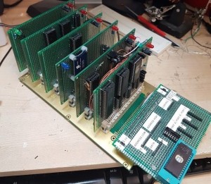
I’m quite taken with the idea of building a computer from multiple little boards, connected to a common backplane. Here’s a particularly sexy example that appeared on Facebook recently:
Now, those people who are VERY experienced at this sort of thing will tell you that the multiple-boards model is actually a bad idea, because each connection between two wires is a potential stability problem for your computer. When electricity flows from one wire to another, any change in impedance at that point will produce a small “reflection” back along the wire. Any slightly dusty connection will make the problem worse. Any intermittent connection may cause a problem when you accidentally nudge your circuit. And so on.
These little imperfections all add up, ultimately limiting how fast you’ll be able to run your computer.
But for me … building a computer in this manner feels like a better way to work, at least for starters.
- This project is very-much a learning exercise. Whilst I know the theory, I don’t know what I don’t know (if you see what I mean). I want to build the computer in different sections so that if I need to, I can test those pieces in isolation. When I’m more certain of my circuit, I can go back later and build “bigger” boards.
- I hope to make prototype boards with my CNC. Smaller, simpler boards are easier than large or complicated ones. The CNC is built for larger jobs (cutting wood) rather than something as accurate as a PCB, so I’ll be right at the limits of what it can do. More complex designs tend to make the CNC “drift” as it cuts, so I’d like to keep the machining complexity to a minimum.
- The design is going to evolve. If I have to throw a board away because my design changes, I’d rather it was only one small board, rather than everything.
- I intend to run the computer very slowly to begin with, so that I can verify that it’s behaving the way I expect. So any imperfections that become apparent at high clock speeds won’t be an issue for a while. I’m not intending to crank it up to 11 anytime soon!
And then … I stumbled-upon RC2014 when a friend bought a kit and put pictures of it on Facebook. This is a build-your-own computer project with similar design goals (small boards sitting on a common backplane) but built around a Z80. The creator offers it in kit-form (everything from just some PCBs, right up to absolutely everything you need) and even does the occasional tutorial at his local Hackspace.
So I bought the kit, with the intention of repurposing it for a 6502.
 (Full disclaimer: this pic was taken by Rob Reynolds for Twitter – I couldn’t take a picture of naked boards because I’ve already started soldering mine.)
Of course, even though the 6502 and Z80 are both 8-bit processors, there are still many architectural differences … but I believe I can adapt the boards to work. Many of the pin designations on the backplane still make sense for a 6502 (16 address lines, 8 data lines, power, clock, reset, and so on) and the ones that don’t can be repurposed/relabelled for equivalent roles. And there’s lots of unassigned pins for expansion.
If I’m honest, I was just quite taken with the nice, simple backplane – which I thought would fare better than a crummy piece of stripboard. Here’s my backplane populated:
 I’ve fitted the connectors, power LED (because why not?), reset pushbutton, and decoupling capacitors. I’ve not bothered fitting the regulator or DC barrel socket, because I have a bench PSU so having a good 5-volt supply is not a worry.
My plan is to start simple: build enough of a computer to run a simple program (even if it’s just running a loop). So I’ll need to build a processor board, ROM board, clock circuitry and the bare-minimum requirements in address decoding.


I love this project. I’m building a 65c02 based system myself.
I was wondering, do you have a Mouser (or Digikey) part number for those DIN41612 connectors? I see many different results when I search for them.
Also, I have those green prototype boards too but mine are much smaller. Do you mind telling me how many solder points are on those boards and/or where you got them?
Thanks!
I’m afraid that initial picture isn’t my computer – it’s from a gent named Ian Bagley, who posted the picture on a 6502-programming Facebook group.
I do have a boxload of DIN41612C connectors, though – I bought them from eBay (co.uk, because I’m in the UK) rather than an electronics supplier. If you search for “DIN41612C Eurocard” on eBay, there’s a box of 20 being sold for 15 pounds. And if you search for “Eurocard prototype boards” you’ll find suitable blank prototype boards for those connectors.