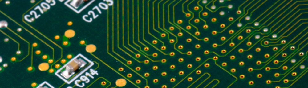
When I first designed the PCB for the EEPROM programmer, I thought I was being very clever by placing the ZIF socket over the top of the DIL pins that go into the Arduino. Then it was just a lot of short, parallel tracks to join them all up.
And whilst it did make the PCB nice and simple to design and understand … it could make assembly a bit of a pain. Nothing major, but enough to be irritating. The few mm that the DIL pins protrude above the PCB could make soldering the ZIF socket a bit of an exercise in fine-balancing of components whilst juggling a soldering iron.
I had assumed it was just me being a bit ham-fisted, but I’ve had some feedback from people who bought the kit that it bothered them too. So: I’ve redesigned the PCB, with a new layout.

It makes the PCB larger than necessary, but to be honest, the PCBs are pretty cheap. The ZIF socket is by far the most expensive part of the project, so it makes complete sense to redesign the PCB to make assembly easier.
So: all new kits sold come with the new PCB, plus an updated assembly manual. I’ve not bothered to increase the price of the kit.
Electrically, it still works the same as before, so the Arduino sketch, supporting utilities and schematic are all unchanged.
The kit is available to purchase on Tindie.