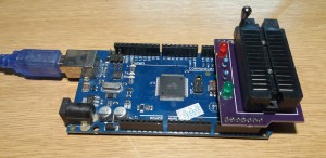
Some time ago, I wrote about my DIY EEPROM programmer driven by an Arduino Mega. It’s a very simple, low-tech project … but has attracted a consistently-high number of visitors to the site and is something I use several times a week.
Recently I’ve discovered the joys of PCB prototyping services, and here I must make special mention of the guys who run OSHpark. I hope to do a proper writeup about the process I go through to design a PCB and then send it to OSHpark for fabrication … but for now I’ll just say that they’ve been pleasantly chatty by e-mail and their service has been awesome, as have the boards I’ve received back from them.
One of my early test prototypes (I wanted to see what size pads and tracks would work best for me, verify that my code to generate Gerbers worked OK, and so on) was to remake the EEPROM-programmer PCB. I’ve just received the boards back and soldered one up and tested it, so it seems like a good time to write it up.
The Blank PCBs
When you order a design to be fabricated by OSHpark, you get three copies of your board back. Which means I can use two of them in a photograph, so you can see both sides:
This is a slight improvement on my original design: I’ve added a row of pads at the top and bottom of the board, for pin headers. These aren’t connected to anything – but they add a bit of stability by fitting into the appropriate connectors on the Arduino Mega.
Making your own boards
If you want to order your own PCBs from OSHpark, just download this zip file (SimpleEEPROMGerbers.zip, 6KB), upload it to OSHpark, and pay. It won’t cost you much (I think it’s $5 per square inch) and for that you get three boards and free postage. I’m in the UK, and I’ve always received boards within a fortnight. If you’re in the US then this will be much quicker.
If you want to examine the Gerbers first, I heartily recommend gerbv – which is available for your modern OS of choice. To use it: unzip the archive, then use the plus icon at the bottom-left of the window to select the files to be loaded. They are treated as separate layers: reorder, show/hide, change colour, and so on.
Population
You need single-row pin headers, double-row pin-headers, a ZIF socket, a red LED, a green LED, and two 470-ohm resistors. Remember to solder the double-row headers before you solder the ZIF socket!
While we’re talking about the ZIF socket – I’d just like to point out that they are a perfect example of “you get what you pay for”. It’s easy to buy them from China via Ebay for pocket change … but the build quality tends to be poor. The very purpose of the ZIF socket is to be open and closed a lot, so it’s a false economy to buy a crap one. I spent about 9 pounds for a good one from Farnell, and the quality difference was obvious.
The Result
I am very happy with the result! The extra pin-headers stop the board from rocking on the Arduino; and because OSHpark boards are double-sided, I can solder components from either side and so make a much more substantial job. The ZIF socket is now soldered on to the board rather than sitting in a DIL socket.
I also have two spare boards … so if anyone wants one (you’ll need to source the other parts yourself) then let me know.


