I found a GPS receiver in a box of junk last week. I can’t quite remember where it came from, but I have a vague recollection of a geeky colleague giving me a boxload of electronics bits when he last moved house. I thought it might be interesting to see how easy it is to use with an Arduino, and write it up here.
It turns out it was quite straightforward, so these are just a few notes in case they’re useful to anyone else. As the communication of GPS receivers is fairly standard, this should prove useful even if your receiver is a different model to mine.
The GPS receiver in question is a Globalsat BR-355. It’s cute, built to be waterproof, has a magnet in it so you can stick it to the car if necessary, and is quite minimalist. It’s little more than a receiver with serial output.
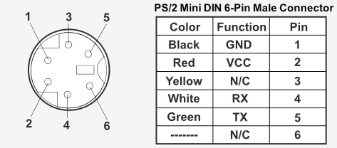
The connector is a 6-pin mini-DIN PS/2 style connector – but don’t try and plug it in where you’d normally connect your keyboard, because it’s certainly not compatible!
The pinout is quite easy to get hold of though, thanks to Globalsat’s website. (Datasheet is here)

To experiment, you’ll need to find yourself a PS/2 socket and solder wires for ground, Vcc (+5 volts) and the Tx line. If you want to talk back to the GPS unit then add another for Rx … but for my experiments, I just wanted to read what comes out of it.
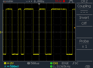
I hooked-up a 5-volt supply, and monitored the Tx line with my trusty oscilloscope …

Behold! Serial data! But if you know what you’re looking for, you’ll see that these voltages are for the RS232 standard (-6v and +6v), which is incompatible with the TTL levels that the Arduino’s serial-port requires. So we’ll need to convert it.
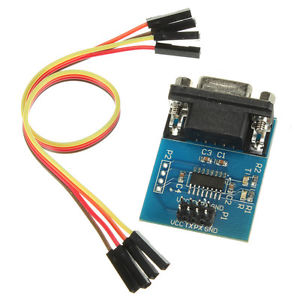
RS232-to-TTL level adjustment has long been the domain of the MAX232 and the like. I couldn’t find one in amongst my component collection … but I did find a couple of these, I’d bought for a long-forgotten project:

It’s a MAX3232, already soldered onto a little board, with a few extra components and a 9-pin D plug helpfully added. To convert the RS232 data from the GPS unit into TTL levels, we just feed that signal into pin 3 of the D plug (don’t forget the ground pin 5), and get TTL levels out from the “Tx” pin on the board itself. Looking at that with the scope gives us:

Ta-da! The serial data now exists between 0v and 5v, which is exactly what the Arduino needs.
The TTL output from this board can then be fed directly into the Rx pin on your Arduino. Something to note here is that models like the Uno only have one hardware serial port – and you’ll probably want to use that to debug your software later. For that reason, I’d recommend using an Arduino Mega for the experimentation, and using one of the other serial-ports for the GPS data. For example: in my experiments I fed the signal into RX1 (which is pin 19).
If the GPS receiver you have already outputs serial data at TTL levels (for example: if it is a device intended to be used in other projects, rather than a consumer-product that is supposed to connect to a laptop) then you can ignore all the above about converting levels. Just wire the data output directly into your Arduino.
That should about cover the hardware side of things. If you have a ‘scope then you should be able to verify that serial data is arriving at the Arduino where it’s supposed to … but even if you don’t, it’s still fairly straightforward. So now we can move on to the software.
A simple Arduino sketch
If you’ve followed my advice, you’ve fed the serial data into an Arduino Mega in pin 19. A really good, simple test to do here is to program the Arduino to take any bytes that appear on serial-port 1 and spit them straight out to serial-port 0.
void setup()
{
  Serial.begin(9600); // serial port that communicates with the PC
  Serial1.begin(4800); // serial port that listens to the GPS unit
}

void loop()
{
  if (Serial1.available()) // if there's a byte waiting to be read
  {
    char c = Serial1.read(); // read it
    Serial.write(c); // send it to the other serial port
  }
}
Note that the GPS receiver sends data (by default) at 4800 baud, but the serial port speed between Arduino and your PC can be anything you like.
Compile this and upload it to your Mega, then open the serial-port monitor. Double-check that the baud rate is set to 9600 … and you’ll see NMEA data streaming through the monitor!
Decoding NMEA data
NMEA data is a stream of sentences. That is: lines of ASCII, terminated by <13><10>, as usual. Each sentence is made up of pieces of data, separated by commas.
The first lump of data always begins with a $, and tells the decoder what data will be in the rest of the sentence. Have a read here for a comprehensive description of each one (or ask Google) … but for the benefit of these notes, I’m going to concentrate on $GPRMC, which is a sort-of “recommended minimum” sentence that GPS software should know how to decode.
This sentence type includes the current time, date, position, and speed. Which is all the information that most people care about, when it comes to GPS receivers!
Here is my cut-to-the-bones code that decodes a $GPRMC sentence and pulls time and date from it. Then it sends it to the serial port so you can monitor it. If you have a spare GPS receiver and Arduino knocking around, this could make a great foundation of a self-setting clock!
char g_buffer[255]; // the sentence being read from the GPS unit
int g_buffer_used; // how many bytes of it we've used

char g_time[10]; // last time we decoded
char g_date[12]; // last date we decoded

bool g_update_clock; // sets true if the time/date has been updated

void setup()
{
  g_buffer[0] = 0;
  g_buffer_used = 0;

  sprintf(g_time, "HH:MM:SS");
  sprintf(g_date, "DD/MM/20YY");

  g_update_clock = false;

  Serial.begin(9600); // to computer
  Serial1.begin(4800); // to GPS
}

void loop()
{
  if (Serial1.available()) // if a byte is ready to be read
  {
    char c = Serial1.read(); // read it
    if (c > 31)
    {
      g_buffer[g_buffer_used] = c; // store it
      g_buffer_used++;
      g_buffer[g_buffer_used] = 0;
    } else
    if (c == 13) // end of sentence! So parse it
    {
      ParseNMEAString();
      g_buffer_used = 0;
      g_buffer[0] = 0;
    }
  }

  if (g_update_clock == true)
  {
    Serial.print(g_time);
    Serial.print(" ");
    Serial.println(g_date);
    g_update_clock = false;
    // (I'm just sending it to the serial-port for now. Obviously it
    // would be rather cooler if we wired an LCD screen in here!)
  }
}

void ParseNMEAString()
{
  int x = 0;
  int p = 0; // start of param
  int i = 0; // which comma-separated parameter we're reading

  while (g_buffer[x] != 0)
  {
    // scan until we hit the end of the string, or a comma
    while (g_buffer[x] != 0 && g_buffer[x] != ',') x++;
    // x now points to either a terminating 0, or a comma

    // we're going to force the comma (if it is one) to be a zero, so
    // that string functions work.
    // But we'll keep a copy of the old char, for the hell of it.
    char oldun = g_buffer[x];
    g_buffer[x] = 0;

    // now ... let's see what's in this parameter
    if (p == x)
    {
      // empty word
    } else
    {
      char* param = &g_buffer[p];

      if (i == 0 && strcmp(param, "$GPRMC"))
      {
        // first word, and it's NOT $GPRMC. So we might as well abort
        // parsing the rest of the string.
        return;
      }

      // so ... if we get this far, then we know it IS a useful string.
      // But for this project, I only care about certain parameters.
      if (i == 1)
      {
        // this is the time stamp, in the form HHMMSS.FRACTION.
        // I only care about the first six characters.
        g_time[0] = param[0];
        g_time[1] = param[1];
        g_time[3] = param[2];
        g_time[4] = param[3];
        g_time[6] = param[4];
        g_time[7] = param[5];
      } else
      if (i == 9)
      {
        // this is the datestamp, in the form DDMMYY.
        g_date[0] = param[0];
        g_date[1] = param[1];
        g_date[3] = param[2];
        g_date[4] = param[3];
        g_date[8] = param[4];
        g_date[9] = param[5];
        g_update_clock = true;
      }
     }

     i++;
     g_buffer[x] = oldun;
     x++; p = x;
  }
}

I know this is an old post but thought I would leave a comment anyway. I use PIC microcontrollers for my projects and have interfaced to the BR-355. Instead of a fancy level shifter on the data line you can use a small signal NPN transistor like the 2N3904. Connect the signal from the GPS through a 10k resistor to the base of the transistor. Connect the emitter of the transistor to ground and the collector to the RX input of your microcontroller. Make sure that the RX input has a pullup resistor to +5 volts (I use 10k).