I need to be able to interact with my computer. I need it to be able to take input, do processing, and produce output.
I have an LCD screen (which would cover the output requirement) and I could implement a keyboard interface at this point … but that seems a jump too far at the moment.
I could do with a link between my computer and my PC. That will make development easier, tests potentially more repeatable, iteration time a bit shorter.
What I need is a serial port. This would cover the input, output, and debugging requirements with not a lot of circuitry. Then I’ll have a way of controlling and monitoring my computer when I come to implement more complicated things (like keyboard and graphics hardware) later.
Such devices are often called ACIAs – Asynchronous Communication Interface Adaptors. So now you know.
Most DIY-computers like this tend to use the 68B50 IC for a serial port. I spent a considerable amount of time studying other people’s designs and experimenting … the short answer is, I couldn’t get it to work reliably. I got to a state where it would transfer bytes, but had a tendency to corrupt the lowest bit.
This is not any sort of comment on the reliability of the 68B50 (as plenty of people use it without issue) … it’s more about the limitations of my intellect. In a fit of frustration I tried the 65C51 instead, and that worked first time! So that’s what I’ve adopted here.
Circuit Diagram

The “/select” pin goes to one of the “/device” lines (see my post on address decoding). When designing my PCBs I’ve started including a line of jumpers so that I can select any of the device lines 1 to 5 (I’m not making 0 selectable because the OS ROM is dedicated to that one).
I’ve put a jumper on the /CTS line so that I can hold it “always active” if I need to. This is because (at the moment) I’m not 100% certain how hardware flow control works. When you’re designing a PCB that’ll take a fortnight to arrive, you tend to add jumpers and extra pads “just in case” … you can always ignore them if you find they’re unnecessary!
Assembled
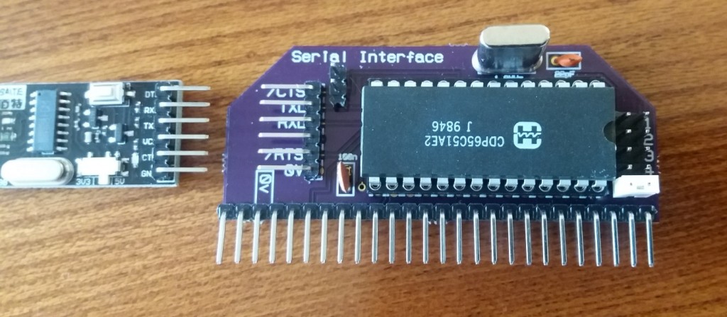
Two weeks to get boards prototyped by OSHpark, twenty minutes with a soldering iron, and:
 I’ve deliberately arranged the pins for the serial port so that they correspond with all those CH340 USB-to-TTL-serial devices that I keep buying from eBay (like the one on the far-left). That way, connecting it up is as easy as finding a strip of five or six (I haven’t connected the Vcc pin) Dupont wires.
Note the row of pin headers on the right – they’re for selecting which device it is. In the picture, it’s set as device 5.
As always, OSHpark provided me with three boards. That means I can easily build (up to) three serial ports, using the device selector pins to make sure they don’t clash. This should prove very useful when I come to do graphics output … which is a topic for a later blog post.
Software
To initialise and configure the 65c51 ACIA, we write bytes to certain locations that correspond with how the board is memory mapped. So here’s how I set up the constants in the assembler:
acia_base = &8500

acia_dat = acia_base ; read here for incoming byte, write for outgoing byte

acia_sta = acia_base + 1 ; serial data status register. A write here causes a reset (actual value is irrelevant)

acia_cmd = acia_base + 2 ; command register

acia_ctl = acia_base + 3 ; control register
I fully expect to mess with the memory map in future – but setting up constants in this manner should mean that all I’ll have to change is the acia_base setting, and everything else will Just Work.
Here’s how to initialise the serial port (which we do on startup):
acia_ctl_config = %00011111 ; 1 stop, 8 bits, 19200 baud, using inbuilt baud rate generator

acia_cmd_config = %00001011 ; No parity, no echo, no tx or rx IRQ, DTR*

acia_txrdy_mask = %00010000 ; AND mask for transmitter ready

acia_rxrdy_mask = %00001000 ; AND mask for receiver buffer full

lda #0:sta acia_sta ; resets the ACIA

lda #acia_ctl_config:sta acia_ctl ; baud rate

lda #acia_cmd_config:sta acia_cmd ; other stuff
To send a byte down the serial port, we just write to acia_dat:
lda #'A':sta acia_dat ; writes an 'A' to the serial port
It is also useful to have code that checks that the byte has been sent (before we try to write another):
.acia_waitforsendclear

lda acia_sta ; get status

and #acia_txrdy_mask ; mask out everything but the relevant bit

beq acia_waitforsendclear ; if result was 0 then bit wasn't set, so repeat the check

rts
Reading a byte is as easy as loading from acia_dat … but we must have first checked whether there is a byte waiting to be read:
.acia_waitforandgetbyte

lda acia_sta ; get serial status

and #acia_rxrdy_mask ; mask out everything except the "byte waiting" bit

beq acia_waitforandgetbyte ; if nothing waiting, then repeat

lda acia_dat ; get the byte

rts
Results
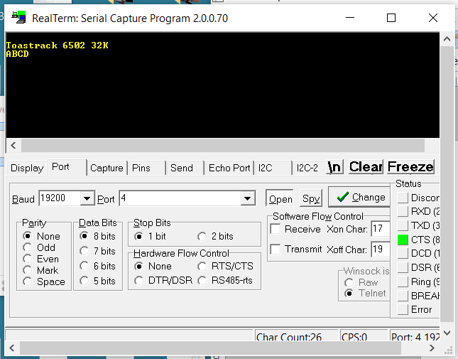
To prove it is working, I’ve updated the OS ROM image so that it sends the welcome message (that’s already going to the LCD screen) to the serial port. Then it sits in a loop, reading from the serial port and then echoing it back:

It works! So I have a computer with working ROM, RAM, and serial port. Now it feels like I need to write some sort of minimalist OS for it …
