For some future projects I intend to use some SRAM ICs, and possibly write some ROMs to fit into a BBC Micro. It seemed sensible to experiment with such components, so I can double-check that I understand how to use them.
I’m starting with something simple: using an Arduino to create an image of a BBC Micro expansion ROM.
By “image”, I don’t mean a picture – a “ROM image” is a byte-for-byte copy of what’s on the ROM, stored as a file. This concept will be familiar to anyone who plays with old console or computer emulators.
This is largely an academic exercise: every commercial expansion ROM for the BBC Micro has already been turned into an image and made available for download from plenty of websites. But this works well for me: it becomes a more predictable and verifiable exercise if I have known “good” data to compare with my results.
This tutorial might prove useful for anyone who has a boxload of unlabelled ROMs that they’d like investigating, or perhaps has some homemade EPROMs that they’d like preserving before bit-rot sets in.
My focus tends towards the BBC Micro, but the principles will apply to lots of other hardware; particularly of the 8-bit and 16-bit generations. As long as you know the pinouts of the ROM you want to read, it should work.
How parallel ROMs are accessed
ROM is “read-only memory” – it’s a lump of data in a physical form, which cannot be changed by the host computer but neither loses its contents when powered-down. It is often used as the known starting point when a computer boots up, even before RAM is initialised or any programs are run from the hard-disc. In the case of the BBC Micro, they can be installed into spare sockets on the motherboard to provide extra functions and utilities.
On the IC, a number of pins are designated the “address” lines, and a number are designated the “data” lines. The general principle is that the controlling CPU sets the address lines high or low (to signify the address of the byte to be read) and then the state of the eight data lines change to represent that byte.
Parallel refers to the addressing and data being a large number of parallel wires – a complete address is represented “in one go”. The alternative would be a serially-accessed ROM, where the address would be transmitted by a series of pulses, using fewer wires. In the 8-bit days such components were always parallel, which tends to make the principle simpler … but involves more wires on your breadboard!
To build our simple reader is straightforward, but repetitive. We wire all the address lines to the Arduino, setting those pins as outputs. We then wire the eight data lines to the Arduino, and set them as inputs. Then we write a simple Arduino sketch that sets each address in turn, and reads the byte that comes out of the ROM. Spit the data out of the serial port to the PC … job done.
The great thing about this (from an experimenter’s point of view) is that it really doesn’t matter how slowly you read the data. It’s a very simple process. If you really wanted, you could demonstrate how to access a ROM with DIP switches on the address lines and LEDs on the data lines.

This is the pinout for the 27128 IC, used in the BBC Micro. 128 refers to the number of kilobits that the IC will store – 128 kilobits, or 16 kilobytes. We can see that there are fourteen address lines (prefixed by an A, and numbered from 0 to 13) and eight data lines (prefixed with a D, numbered from 0 to 7).
I’m using an Arduino Mega to do the reading – for no other reason than it has enough digital pins to be feasible! If you don’t have a Mega but do have something smaller like an Uno then you could use 165 or 595 shift registers to manipulate the address lines (see my other article) but to include that in this blog post would just complicate things.
Wiring up
Download my RomReader Arduino sketch and load it into the Arduino app.
Stick your ROM on a breadboard. Make sure that the power rails on the breadboard are connected to your Arduino.
There are a few pins on the IC that need wiring to +5v or ground, depending on their purpose:
- GND (pin 14), /CE (20), /OE (22) should be wired to ground.
- Vpp (pin 1), /PGM (pin 27), Vcc (pin 28) should be wired to +5 volts.
Next we need to connect the address and data lines. At the top of the code you’ll see where I’m designating which digital pin connects to which address or data line on the 27128. As it doesn’t really matter which pins on the Arduino you use, I recommend that you just connect them in whatever way keeps the wiring as neat as possible, entering the pin numbers into the code as you do. I’ve recently bought a lot of connecting wires, which come as a ribbon cable. Breaking the ribbon cable into lumps of half a dozen or so and connecting them all at the same time helps to keep things neat.
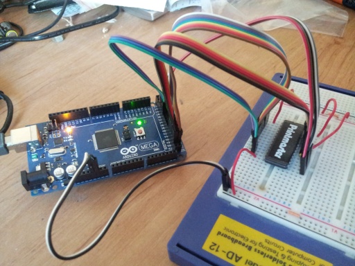
Simple, primitive … gets the job done.
That’s about it for the hardware!
The software is fairly simple. In setup() the address pins are set as outputs, and the data pins as inputs. The serial port is initialised at 9600 baud, and is used to send data back to your PC (open the serial monitor to see).
In loop(), the code cycles through addresses 0 to 16383, in blocks of 16. I’ve done this only to make printing the data slightly simpler later (I put 16 bytes of data on each line when outputting the hex). The code sets the address on the address lines, then reads the byte back from the data lines and stores it in the array.
When the array has been filled, those sixteen bytes are printed in hexadecimal to the serial port, along with an ASCII dump. Capturing that text and processing it into binary data is left as an exercise for the reader!
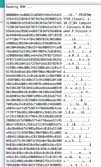
Results of reading the PrintMaster ROM.
[To the EEPROM Writer Project page]
Hi, any ideas on how to write to the sram?
Assuming you’re using parallel SRAM … yes, it’s very similar to reading ROMs. There’s a R/W (“read, not-write”) pin that you’ll need to pull low when you’re writing a byte. Otherwise, it’s the same as a ROM. I’ll do a proper write-up eventually. I have a half-finished article on making a cheap EEPROM writer which works in exactly this way.
However, if you’re using serial SRAM … never used that, and don’t have any need to for the forseeable future. So I can’t help you with that one.
Hi, thank you for sharing the arduino code! I am a newbie trying to work out the “exercise for the reader” … with no luck :(.
May I ask you to complete the explanation with the capture and binary processing part? Would be much appreciated!
It would be worth looking at my accompanying blog post on building an EEPROM programmer (http://danceswithferrets.org/geekblog/?p=496) – as this has the same ability to read ROMs, and I’ve provided a command-line executable (for Windows) that does what you want.
Do you mean “eprommer_v2”? Looking at the readme.txt i got that you can read from a binary file:
-read – reads EEPROM or ROM into binary file
My problem is: i have my serial monitor full of hex numbers, how can i extract them and turn in a binary file?
(Thank you very much)
I meant that the programmer project is basically the reader project AND a writer, AND the command-line tools to make things easier. So it might be good to follow the later project, and use the tool provided. The command-line tool talks to the Arduino directly so that you never need to see the hex codes.
But if you’re a programmer and want to write a program to decode those hex values, then you need to save the output from your serial monitor, then write a quick program to read it in, line by line, and write a binary file.
Got it: thank you very much!
If I want to use this code to read a 256k DS1235YW,
I should add :
static const int kPin_A14 = xx ; <= xx MEGA Pin….
pinMode(kPin_A14, OUTPUT);
digitalWrite(kPin_A14, (addr & 16384)?HIGH:LOW);
for (addr = 0; addr < 32768; addr += 16)
¿ something more ?
Thanks.
how can i edit rom image??in eprom programmer windw app
The app doesn’t support editing. It’s for reading and writing. Use the app to save the file, then use your favourite binary editor (I use HxD) to modify it.