There’s only so long I can sit and watch one digit of a hex-display count from 0 to 6, even when I’ve been drinking. Particularly when that circuit is messy, and the sundry tools (like bench power supply, multimeter, logic probe and oscilloscope) are covering half my desk, leaving me little room to do any proper work.
So before I start adding anything new to my computer, it seems a good idea to clean-up what I have. Take the really crap temporary stuff, and make it … well, if not actually good, then just slightly less temporary.
There’s a lot of jumper wires and temporary hacks, and it’s all a bit fragile. We can improve it. A good way to start would be to make better PCBs.
The CPU Board
The CPU-Stripboard-Of-Horror is gone, replaced with a PCB:
 My CNC doesn’t really do super-fine work, so I’ve err’d on the fatter side when it comes to track tolerances … but it’s still a substantial improvement.
 I’ve taken advantage of the fact that boards can be installed into the RC2014 sockets backwards and designed the board to use this, as for this board it involves fewer crossovers.
The Address Decoder Board
Evolving slightly from the design in part two, my address decoder now looks like this:

This circuit uses a 74LS00 and a 74LS04. The numbers on the far-left and far-right are the RC2014 pin designations, and the others are the pin numbers I’ve used on those ICs.
This circuit provides the same select line for the OS ROM as before and another for /THIRD. So named because it selects for addresses in the third-quarter of the 6502’s address range (from &8000 to &BFFF). I intend to use this for my first tests with peripherals.
It also adds a /WE “write-enable” line, which I’ll need for writing to RAM or peripherals.

 You’ll note I’ve put a jumper in for /THIRD. That’s because I can forsee this being repurposed soon, and putting a jumper in means I might not have to throw away the entire board when I outgrow the current design.
ROM Board with a ZIF socket
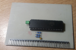
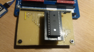
I’ve also made a PCB for the OS ROM – not that there’s anything wrong with the RC2014 one, but this one is designed to be larger, to seat a ZIF socket … and to be mounted horizontally. That’ll make it considerably quicker to iterate new firmware updates, before my computer becomes good enough to be properly programmable. When that happens, I’ll return to using the RC2014 ROM board.

 I’ve mounted two nylon pillars to the bottom corners of the board, so that pressing down on the board doesn’t put any rotational torque on the backplane connector.
Putting it together …
And for the PCBs, thanks to …
The PCBs from today’s episode were all handcrafted by the engineering arm of Oddbloke Megacorp Industries … or “Dad”, as I usually call him.

