So … at the end of the last thrilling installment, I had a load of blank PCBs that were intended for use in a Z80-based computer, and I had a vague idea about repurposing them for a 6502 instead.
For my first iteration of a computer, I’m going to build something that just executes a program stored in an EEPROM. And that program is just going to be a simple loop. For that, I need a CPU board, a ROM board, and a bit of glue logic.
The CPU Board
I had such great ideas about repurposing the Z80 boards with minimal effort, didn’t I? Well, it’s just not feasible to repurpose the CPU board – the pinouts of the two processors are too different. So I built a CPU board from stripboard:

Don’t look too closely, for that way madness lies.
I hate stripboard. Really, I do. It seems like such a good idea, but it is just not possible to make a nice job of soldering one. And it was quite a complicated amount of wiring, and I’m not the world’s fastest solderer, so this ugly picture represents about three evenings of soldering and swearing and muttering to myself.
I’m not showing you the solder side. Really, I’m not. No-one needs to see that.
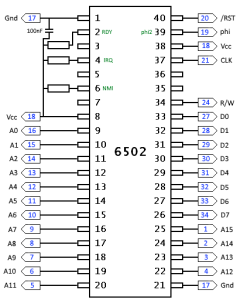
Here’s the schematic I worked from. The numbers in blue are the pin designations on the RC2014 backplane:
 The ROM Board

The RC2014 ROM board, though, was much simpler. I started by visiting the RC2014 website and capturing the schematic for the ROM board (the creator has very gratiously made all his schematics available online). I drew over the image to mark where I would splice wires to map the ROM for a 6502.

My modifications to the RC2014 ROM card. (Click to see full size version.)
Note that I’m not using the 74LS32 – I’m just using the pads it requires as convenient places to splice the wires. You might also notice in the schematic where I’ve relabelled some of the backplane pins, where I’m repurposing them.
I’m using a 32K EEPROM. I intend the OS ROM to be the second half of that, in the final 16K of the 6502 address space – from &C000 to &FFFF. That’s the same as the BBC Micro.
When the 6502 starts (or is reset) it reads two bytes from addresses &FFFC and &FFFD and then begins execution from the address formed by those two bytes. So nearly all 6502 computers put their “operating system ROM” at that end of the address space so that the ROM image contains these two memory locations.
I’ve designated one of the pins on the 40-way connector the “ROM select” line. That connects to the /CS line on the ROM. I’ll drive it from some simple address decoding logic.
The first half of the EEPROM is unused for now, but eventually I’m considering putting BBC BASIC in it. But that’s for another day.
The Glue Logic
In a 6502-based computer, all devices (ROM, RAM, interfaces, displays, and so on) should be “memory mapped”. This just means that when designing the computer, you add “address decode logic” that decides which device should be active according to what address the CPU has put onto the address bus. Then, when the processor reads or writes those locations, it’s not necessarily accessing RAM or ROM – it could be accessing any number of peripherals.
This is one of those areas which can get quite complicated in a micro like the Beeb, but for my first computer can be very simple. As the only device I need for this circuit is the ROM, I could technically have it selected all the time. But it seems a good idea to do a minimal select circuit, to prove it works.
This minimal circuit decides whether the OS ROM should be selected by looking at the highest two address lines – they must both be high to select it (/OSROM goes to the select pin of the EEPROM). The other gate ensures that /OE (output-enable) is only asserted when the IC is reading, and during the phi2 stage of the cycle.

The gates in the diagram above are NAND gates. These are AND gates, with the output subsequently inverted. They are typically provided by the 74LS00 IC. This address decoder is half of that used in Grant Searle’s minimal 6502 circuit, which I’ve found to be an enormously useful design!
The Clock and Address Monitor
A computer needs a clock circuit. This is just a simple pulse, that acts like a metronome for a musician: for each ‘tick’, the processor performs the next item in its sequence. Instructions may take one or more ticks to execute.
At some point in the future, I’ll be seeing how fast I can run my computer … but for now, I want it to run nice and slowly, so I can see that it’s doing what I expect. So I’m going to run the clock at 1 Hertz – that’s one tick per second.
For now, I’m using an Arduino as the clock generator. Partly because I have ideas about being able to adjust the speed of the clock, go into single-step mode, and so on, and an Arduino would be a nice way to do it. But also because I’m using the Arduino as an address monitor – it reads the status of the sixteen address lines, turns it into hexadecimal, and displays it on a 4×7-segment display I picked up on eBay. By seeing the addresses tick over at 1Hz, I’ll be able to verify that my program is executing.
The Program
The source looks like this. Assembled at &8000 and then written to an EEPROM using my DIY EEPROM programmer. As you can see, it’s just a trivial program – a few “do nothing” instructions, followed by a jump back to the start.
ORG &8000
    equs "This 16K isn't being used yet. Just placeholder for now."

ORG &C000
.start_here
    nop
    nop
    nop
    nop
    jmp start_here

ORG &FFFA
    equw start_here ; NMI address (not used at the moment)
    equw start_here ; RESET address
    equw start_here ; IRQ address (not used at the moment)
My assembler of choice is Rich Talbot-Watkins’ excellent beebasm.
Reset Circuit
The CPU needs to be forcibly reset on power up, otherwise it tends to start in an indeterminate state and behaves unpredictably. Computers that use the 6502 have a circuit in them that forces the computer to reset on power-up (the BBC Micro does it with a 555 timer). For now, I’m not going to bother with one of those … that’s why I fitted the reset pushbutton to the backplane. Reset action will be triggered with a Mk. 1 finger.
The Results

First iteration of my computer. (Click to see a bigger image.)
And here it is – the first iteration of my computer! The jumble of white wires are the sixteen address lines going to the Arduino, which is on the left (cable being held-down with my keyboard). The stripboard CPU board is visible at the back, and the small breadboard on the right has a 74LS00 on it, acting as the address decoder.
I set up my digital SLR on a tripod, and took a photo for each second the address monitor updates. What you’re seeing is (after I reset the CPU) a few cycles of unpredictable addresses while the 6502 initialises (&01FC, &01FB, &01FA) followed by the two addresses where the CPU reads the start address (&FFFC, &FFFD) and then the addresses it follows as my program runs (&C000 to &C006).

The addresses as they appear after the 6502 has been reset.
It’s also interesting that the frame moves a bit between some shots, even though I’ve put the camera on a tripod – my fat fingers pressing the shutter release is enough to move the camera just enough to be irritating. Clearly those remote triggers are worth buying!
It’s worth mentioning that the first 6502 in my spares box didn’t work with this circuit, but a later revision (a 65C02) did. Apparently earlier processors had a minimum clock speed they need to run at (a few kHz) or they behave unpredictably. But the 65C02 seems to be able to single-step. The recommended way to run it is to keep the clock pin in its high state while you’re waiting.
So there we are! My first, pointless computer; doing what is barely even “Hello World”. It has no RAM, nothing to interact with, and nothing to control. But it is working, and it gives me something to build on.
Great project and write up. Would you be prepared to share the Arduino code please?